Saturday, December 31, 2005

Tamrac Expedition 7 Backpack - Part 1

The most desired item on my Christmas list was a Tamrac Expedition 7 backpack. Luckily, my wife was kind enough to buy it for me.

I've actually been wanting a backpack for quite a while now. As my camera bag reaches the 15 lbs mark, it has started to become a bit of a burden to support on one shoulder. Carrying it on a couple of the 1 mile (each way) hikes I've gone on has been very difficult. I found myself repeatedly shifting the bag to different positions just to stay comfortable: Right shoulder, left shoulder, right hand, left hand, cradle it with both arms, etc. There have been a few hikes that I just didn't have the motivation to go on, simply because I knew how painfully far I'd have to carry that bag.

For this reason, I've been thinking about shifting to a backpack for about 8 months now. I almost hurried and bought a backpack before my trip to Seattle last May, but decided I didn't want to rush into it...I wanted to think about it some more. After all, a backpack isn't a godsend. It does have one major downside, which is the lack of accessibility to equipment. Every time you want to get out a new piece of equipment, you need to take the backpack off, open it, get what it is you want, close up the backpack (can't just leave it unzipped like a shoulder bag), and put it back on. A major pain.

So, afraid that I wouldn't like the decreased accessibility, I put off purchasing a backpack. However, every single time I had to carry that heavy bag on my shoulder, I though a little bit more about getting a backpack. With Christmas coming up, and my choice of tripod undecided, I figured this would be the perfect time to ask for one.

So why did I choose the Tamrac Expedition 7? After comparing backpacks from many different vendors, the Tamrac Expedition series seemed to have the most features and also, even more importantly, seemed to do the most to minimize the accessibility downside of using a backpack. I'll explain this in a minute. Looking at the Expedition series, only the 7 and 8 models seemed to have enough room for the equipment I wanted to carry, and only the 7 and 8 had the extra waist strap to help spread the weight of the pack across your body.

Comparing the two models, the 8 seemed a bit large for my body (I'm not a very larger person...about 5'7" and 160 lbs), and it seemed like it had WAY more room than I needed (though now that I've loaded up my 7, I can see how the 8 would have been a good idea). So, I settled on the Tamrac Expedition 7 as my pick.

So back to the accessibility issue. Well, the thing I liked best about this backpack was that it had the most room and most convenient arrangement for expansion. It has all sorts of places where you can connect on an extra lens case or a pouch. There are 4 on the side, and 2 on the shoulder straps. In addition, although not an official attachment slot, there are 4 places on the waist belt which could be used to hold expansions...2 would work well for carrying lenses, and 2 are perfect for my filter pouches.

So which accessories did I decide on? First, I got a large pouch, which is the perfect size for holding my Sigma flash unit. Next, I got a large lens case so that I can get access to switch off a lens easily (though now I wish I had asked for 2). When out hiking, you are bound to get thirsty, and I'd hate to carry a water bottle separately, so I got the water bottle attachment. I also got a 4-slot memory card/battery pouch that attaches to the shoulder strap. This way I can swap out the items which I change almost as often as my lenses. Finally, I got a pair of cinch straps, which are just for generic use, however I decide to use them...like maybe attaching a light rainjacket/windbreaker to the side of the backpack.

So that gives you an introduction to the backpack...why I wanted one, what I thought about, how I decided on what I wanted, and what I ended up getting. The post is getting a bit long at this point, so next time I'll post more details on the backpack now that I have it in my hands...my thoughts on construction and features, how I loaded it up, and what I think I'd like to add. I'll post some pictures of it. However, being that I'm sick right now (see yesterdays post) and stuck in the house, I'll have to leave my thoughts on actually using this backpack until a future part 3.

Update: Tamrac Expedition 7 Backpack - Part 2
...click here to read more!

Friday, December 30, 2005

A Merry Christmas and an Unhappy New Year

Santa was pretty good to me in the photography department this year. I put together a list of equipment I wanted for Christmas, and I got a good portion of it. I'll talk about the various pieces of equipment individually over the coming days, but here's a quick summary of what I got:

Tamrac Expedition 7 backpack
5 accessory attachments for the backpack:
      lens case
      accessory pouch
      water bottle & pouch
      4 pocket memory card/battery pouch
      two cinch straps
Plamp + 1 foot extension
McClamp
Better Beamer
Lumiquest Promax System (80-20 + 3 reflectors + diffuser)

The item I really wanted most was a new tripod and a ballhead. However I couldn't decide on exactly which one I wanted (and I'm still trying to figure it out) so that got left off of my list. Unfortunately, when trying out some of my gifts the day after Christmas, one of the locking levers on the leg of my current tripod snapped off. At least it's stuck in the leg expanded position, so I can still make use of the tripod...I just can't close that one leg all the way. But it's kind of pressing the issue now, so I have to figure out pretty soon which equipment I really do want so I can order it.

So, gifts from Santa was the Merry part of Christmas, but (despite how it might sound) the broken tripod is NOT the unhappy part about the new year. No...the unhappy part is that, despite the fact that I have the entire week off from work, I can't go out hiking with my backpack, or trying out my better beamer on the winter birds. And why not? I'm SICK!!!!!

I came down with a cold the other day. Not much of a big deal...I deal with colds all the time and don't let them concern me much. However, the first day I went out to the grocery store, and later that night I came down with a fever. Now I have a bit of a cough and little bit of a sore throat. It's probably best if I don't go hiking through the winter weather right now, so I'm confining myself to the indoors. Maybe I'll find myself some abstract macro subjects around the house to take pictures of...make use of the Promax and the clamps.
...click here to read more!

Monday, December 26, 2005

Grid wall instruction

UPDATE (June 21, 2006): I've made a few changes to the design, making on site assembly (at the art show) easier and probably even lowering the total cost by $20 or so. Read through this posting first, then take a look at the changes I made here

I promised back in September that I'd get these instructions up in the next couple days. So much for that, but better late than never, so here we go. But before I get into the details, just to clarify for those unfamiliar: 5" = 5 inches, 5' = 5 feet. Don't mix them up

Cut your conduit

First thing we need to do is cut up the conduit. We'll need 22 pieces of 10' long, 1/2" electrical conduit. Take 18 pieces of conduit and cut them all the same: Cut off a 5' 6" section (66"), a 3' 1/8" section (36 1/8"), and your remainder should be about 17 5/8". Next, take 3 more pieces of conduit and cut each one into 4 equal pieces or about 2' 6" (30") each (minus whatever is lost to the sawblade). Finally take the last piece, cut off two 4' 6" sections (54"), and scrap the remaining foot.

In addition, we'll also need 1 piece of 10' long 3/4" electrical conduit, which will be cut into one 5' section and two 2' 6" sections.

Drill and assemble the 9 panel frames

Next, we will need 36 corner braces. I used some heavy duty 3" braces. They are 3" long on each side and have 2 holes approximately 15/16" and 2 9/6" from the corner. If your dimensions are different, you will need to drill some of the holes differently in the next step.

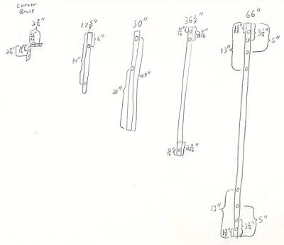
Now we need to prepare the tubes for assembly. Take all 18 of the 66" sections, all 18 of the 36 1/8" sections, all 12 of the 30" sections, but only 6 of the 17 5/8" sections (the other 12 can be set aside for now). First, use a flat file to smooth down the cuts on each end. Now, what we need to do is drill the necessary holes in them according to the diagram below.

There are a few important details. First, it is important that these holes be drilled as accurately as possible. It would be best to use a drill press with a table vice and a production stop. That way you can be sure the corresponding holes get drilled at the same location on all 18 pieces so that they all line up later. Second, you want these holes to be drilled parallel to each other, so that both the entry and exit holes line up. With a drill press, this is no problem when drilling a square piece of stock. However, with a round piece of stock (ie: no flat surface) it's VERY easy to rotate the stock at an angle.

This problem would best be solved with proper machining facilities. However, doing this out of my basement, I had to improvise. The trick I used was to purchase a 6" long 1/4" bolt and small 6 " magnetic level. Assuming your drill press table is level, and your drill bit is perpendicular to the table, you drill your first hole in each piece at any angle. Then for subsequent holes, you place the bolt sticking up through the original hole, stick the level onto the bolt, rotate the piece until it's level (ie: the bolt is pointing perfectly up), clamp it down in the drill press, and drill your hole. After all holes are drilled in each piece, use a round file to clean out the holes and a flat fill to remove any left over burrs.

OK, onto the diagram. Using a 1/4" drill bit, drill holes into each piece of conduit according to the diagram below (click the picture for a full size image).


Now with all the holes drilled, we need to assemble the 9 sections of panel. For each one, we will need two 66" conduits, two 36 1/8" conduits, 4 corner brackets, 16 bolts (1.5" long, 1/4" diameter) and 16 nuts (1/4" diameter"). Connect them together so that they end up like the following picture (note how the excess length of the bolt is on the INSIDE of the frame.


Now that each frame is assembled, you should be left with 4 unused holes on each of long sides. These holes will be used later by the bolts that hold the sections together to form an entire wall. We're not ready for that step yet, but there is one thing you should do at this point. In theory, if you machined all of you pieces identically, then all the holes should line up perfectly. However, in reality there probably are going to be slight differences in the way things line up. To make assembly easier, it would be nice if these holes were opened up slightly to allow some room for error. To do this, I took a hand drill with a 1/4" drill bit, put it in each hole, turned it on, and rocked the drill around to all angles (kind of in a circle). This widens the hole up slighly to allow room for error and to make assembly easier. Then I just filed down the holes again.

Attach grid wire to each panel frame

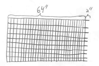
Once you have that done for all 9 sections, then we need to apply the grid wire. Get a 50' roll of 36" wide grid wire (the holes in the grid should be 2"x4"). If you cut this VERY carefully, you should be able to get all your cuts out of 1 roll (with about 6 inches to spare). You want to cut off 9 section that are 64" long. However, no matter how you cut the wire, either the piece you are currently cutting or the next piece will have some nubs sticking out at the end. What you really want to do is cut the wire just before the 66" mark. The extra 2" nubs will be on the piece you just cut off. Then you can trim them off the current piece you that you have a 64" piece of grid. The diagram below should make this more clear. It depicts the nubs on the right side. After you trim off the 2" nubs, the right side and left side would look the same.


Now you want to take each section of grid wire, grind off any sharp ends from your cuts, set them in place in each of the 9 frames, then use a couple dozen 7 inch zip ties to secure the grid wire in place. When you attach the zip ties, it's a good idea if you space them out evenly, and its also helpful if you attach them at the same locations on each panel. After attaching all of the zip ties and pulling them all tight, you can now use wire cutters to trim off the excess.

Assemble 9 panels into 3 walls (3 panels each)

Now you should have 9 panels built. Next step is to assemble each of the 3 walls (and you will need to do this each time you set up your display). Take 3 of your panels and lay them on the ground. Take two 17 5/8" pieces and place them between each pair of panels at the top edge, so that about 1" of tubing will stick out over the top of the panels once they are assembled. Now take 4 of the 30" pieces, and place these at the bottom so that they stick out about 16" to form the legs, one on the left end, one on the right end, and 1 between each pair of panels. Now we need to bolt them on. To do so, use 1/4" bolts and nuts. Use a pair of 2" length bolts to attach each of the 2 legs on the ends. Then use a pair of 2.5" length bolt on each of the middle legs and each of the upper arms.

One note before bolting these down. You may notice that the heads of some of the other bolt on the 3 panels will be sticking out, getting in the way of each of these tubes you try to bolt on. My solution was to take a pair of 1/4" hex nuts, tape them to the jaws of a vice so that they line up (one on each jaw), mark each piece of tubing where a bolt will be in the way, place the tube in the vice so that the taped hex nuts line up with the marks, then tighten the vice to indent there areas. You can kind of see how this looks in the top picture above. I also found that the straps from the zip ties also got in the way a little. To deal with this, I just place that section of the tube in the vice (without the hex nuts...using the bare jaws) and tightened it down to indent it JUST A LITTLE BIT. Don't overdo it. Once you have this done for all the pieces, go back and assemble them with the bolts as indicated above. Repeat assembly instructions for each of the other 2 wall.

Attach the walls to your canopy frame

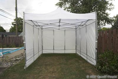
If you followed instructions correctly, you should now have a full wall, approximately 9.5' wide (I never measured it exactly). This should fit perfectly between the legs of an EZ-Up canopy. Take each of the 3 walls, stand them up between the canopy legs, then zip tie them to the legs using some heavy duty zip ties. I initally took 2 of my 7" zip ties, connected them together to form a longer one, and used this. However, I have since purches some heavier duty 11" ties instead. Whatever you decide, you will want to use 4 ties on each wall (one at the top and bottom of each end).

Assemble crossbar supports

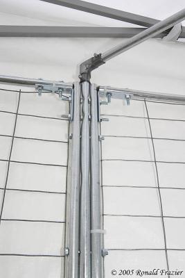
Your display should now be pretty sturdy. It could probably stand on it's own this way just fine. However, I wanted to be a little more careful, and add a little more support. And that's what the little 1" nubs sticking out at the top of each wall are for. I built some cross supports. I put one long support going from the left wall to the right wall, and the a shorter support going diagonally from each of the side walls to the back wall. When all 3 are attached, you get a sort of triangle shape, but with the points of the triangle flattened off . You can see these supports in the photo below.


To consturct the longer support, take the 5' section of the 3/4" conduit, and slide one of the 54" section of 1/2" conduit into each end. You will need to find a way to bold these pipes together tightly. The easiest way I found was to use soome litle threaded inserts...the kind used to add metal thread holes into a wooden object. I used ones that are threaded to accept 1/4" bolts. I then drill a hole in each end of the 3/4" conduit big enough for the insert to poke through, then placed the insert through the hole from the INSIDE of the conduit sticking out. The problem here was, because of the shape of the threaded insert, there was no longer enough clearance inside the conduit for the 1/2" conduit to fit. To fix this, I had to file off a lot of the insert to make it fit better. It's really difficult to explain this in words, so the pictures below should make this clearer.


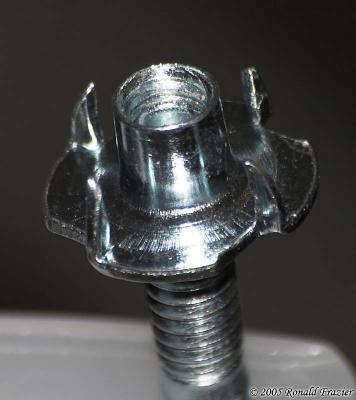
unmodified threaded insert


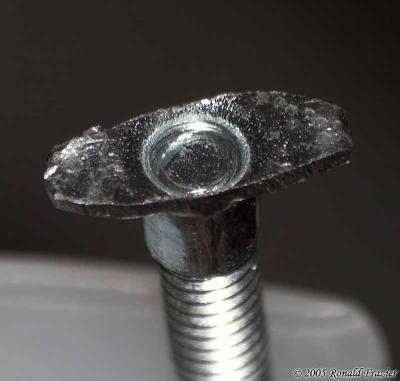
threaded insert, filed down


threaded insert installed in cross bar


Instead of doing all of this, you could just use a single long piece of 1/2" conduit for the support. However, you then have to make sure to cut it at the exact length, and you need to fit this nearly 10 foot long piece of conduit into your vehicle. With the design I used, the length is adjustable, and it disassembled to a much more manageable length.

Now you need to repeat this process for each of the smaller supports. For each one, use one of your 2' 6" sections of 3/4" conduit along with two of your remaining 17 5/8". Repeat the process of drilling holes and inserting the threads.

Finally, you will need to attach each of these sections to the walls. You'll need to use six L-connectors for 1/2" electical conduit, as shown in the image below.


Loosen the bolts on the support bracket, attched on of these L-connectors to each end, tighten down the screw on each connector, puth the entire support in place, tighten it down on the wall section, then tighten the bolts on the support.

Enjoy your grid walls

This is certainly no easy task to get these all assembled, but if you made it this far...congratulations.
...click here to read more!

Tuesday, December 13, 2005

I won in a photo contest

I just found out last week that a couple of my photographs won in a contest. The University of Michigan - Dearborn held a photo contest in September: A Day in the Life of UM-Dearborn. There were 4 categories:

Student Life - photo of students
Faculty/Staff - photo of faculty/staff
Nature - must be on campus
Black & White - open category, but must either be on campus or include student/faculty/staff.

You could submit up to 5 photos. I submitted 4 photos: 2 in the nature category and 2 in the black & white category. I skipped the other categories....people really isn't my specialty. Well, 2 of my photographs won. Here are the winners (click on each picture for the full size image.

Living Among Us
Nature


The Mardigian Sky
Black & White


Also, here are the 2 photograph that didn't win.

The Shining Sun


Reflected Design


As a winner, my photographs will be professionally enlarged and framed. They will hang in the University Center for 1 year. After that, I get to take them home and keep them. I'm really quite excited.
...click here to read more!

Monday, December 12, 2005

Fall colors in Traverse City

OK, I'm guilty...I haven't posted here in a while. I've been a bit busy with some other things around the house, so I haven't had a whole lot of time for photography lately, and when I do have the time it's mostly been unexciting stuff to write about (just more picking out, working on, and framing prints).

However, one thing worth writing about (which I should have posted about a month ago) was a fall color trip. The last weekend of October, we took a trip up to Traverse City to get some shots of the last weekend of peak fall color.

The first day, we left home early to begin the 4.5 hour trip up to Traverse City. Once we got near the area, we diverted onto some smaller back roads to get a better look at some of the scenery. A few pretty sights, but nothing spectacular. Once we got into Traverse City, we stopped for lunch, and then started a trip up the 16 mile long Old Mission Peninsula.

At the tip of the peninsula is Old Mission Point Lighthouse. We stopped here for some pics. It was difficult getting any good shots of the lighthouse at this time of year, since the sun is so low (as you can see in the first picture below). The first surprise here was how low the water level of the lake is. The lighthouse is supposed to sit just off the edge of the water, and then there is supposed to be a very shallow (about 1-2 foot deep) sandy and rocky bar that extends out about 400-500 feet. However, this year the water was so low, that entire bar was exposed. In the following picture, I'm a little more than halfway out on the bar. You can just barely see the lighthouse nestled in the trees.


From that point, the water should have appeared to go right up to the tree line, but not this year. Here's a better look at the lighthouse and also a cabin near the lighthouse.


After leaving the lighthouse, we headed back down the center of the peninsula (we came up the west shore) for a different view. There were some pretty sights, but the best were from the vineyard of Chateau Chantel. I got the following shot before heading inside for some free wine tasting.


After getting back to the city, we checked into our hotel, went out for dinner, and then hurried for a drive around Lake Leelanau before the sun set. We just winged it, taking random roads here and there, and got some nice shots from that drive.


By now it was getting dark. We went to the beach to see if there'd be any sort of sunset color, but the sky wouldn't cooperate. So, we headed back to our hotel and called it a day.

The next day we slept as long as we could, but we were up early, and because of the time change, that made it even earlier. And with the short days, the sun comes up so late. We didn't want to get anywhere too early, so we sat around for a few hours before heading out. We took a drive towards the Lake Michigan shore. Along the way, we saw a really cool looking red barn:


Then we took a drive through the Pierce Stocking Scenic Drive in Sleeping Bear Dunes National Lakeshore. We went here last year in the spring, but it was quite a different sight once all the trees are colorful.


We then headed home down the shore, stopping at a few lighthouses along the way, and got a few nice pictures.

We found this nice little lake view in Empire:


This is also were we saw the Manning Memorial Lighthouse:


The waves were really breaking at Frankfort North Breakwater Lighthouse:


There was some painting and restoration going on at Point Betsie Lighthouse, so we couldn't any good shot without scaffolding getting in it.


Finally, we hit the Manistee North Pierhead Lighthouse:


We didn't want to get home too late, and the day was getting short, so we headed home after this. It was a nice enjoyable trip.


I plan to put up a few more updates this week. A few photos of mine won a contest. I'll post about that tomorrow. I'd also like to share my experiences repairing my Sigma flash, and finish writing up the instructions on building my display panels (I got them half written up 2 months ago and never finished). Hopefully those 2 will make it up later this week.
...click here to read more!